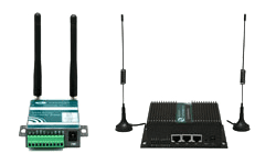
Serial port on E-Lins 4g sim router
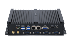
You may have noticed that there are green terminals or DB9 ports on E-Lins 4g sim routers, what are they for? If you have used PLC, you should know that the communication between PLC and control equipment is basically based on serial communication interface, which is controlled by its corresponding communication protocol, and for serial communication interface, including RS232, RS422 and RS485. RS422 will be relatively slightly less, and RS232 and RS485 are used more. The terminal or DB9 port of the E-Lins router is used to support RS232 or RS485.
RS232 interface standard: The RS-232 interface conforms to the interface standard of serial data communication formulated by the Electronic Industries Alliance (EIA) of the United States, and is widely used in the connection of computer serial interface peripherals. For example, some old PCs are equipped with RS232 interface.
The working mode of RS232 is single-ended working mode, which is an unbalanced transmission mode. The logic level of the signal at the transceiver end is relative to the signal ground. RS232 was originally DET (digital terminal equipment) and DCE (data Communication equipment) one-to-one communication, that is, point-to-point, is generally used for full-duplex transmission, of course, it can also be used for half-duplex transmission.
In addition, RS232 is negative logic, the logic level is ±5~±15V, the transmission distance is short, only 15 meters, the actual application can reach 50 meters, but the longer distance needs to be modulated.
At first, the standard physical interface of RS232 was 25 pins, because 9 pins are commonly used, and then the DB9 connector was basically used. Among the 9 pins of DB9, not all signal terminals are used. For example, RTS/CTS is only used for switching between transmission and reception in half-duplex mode, while in full-duplex mode, due to the configuration Two-way channel so no need. Generally speaking, in full-duplex mode, only three lines are enough for RS232 standard wiring, two data signal lines TXD/RXD, and one signal ground line GND. The way to connect the two sides is to cross-connect TXD and RXD, connect the signal grounds directly, then short-circuit their respective RTS/CTS, DSR/DTR, and leave DCD and RI in the air.

 Networking
 EMBEDDED SYSTEMS
 Switches
 Wireless Solutions
 Industrial Computer
 Cloud Services


